Knowledge Library · Tank & Terminal Integrity

TANK & TERMINAL INTEGRITY

Terminal integrity is built through Operational Trust at every interface.

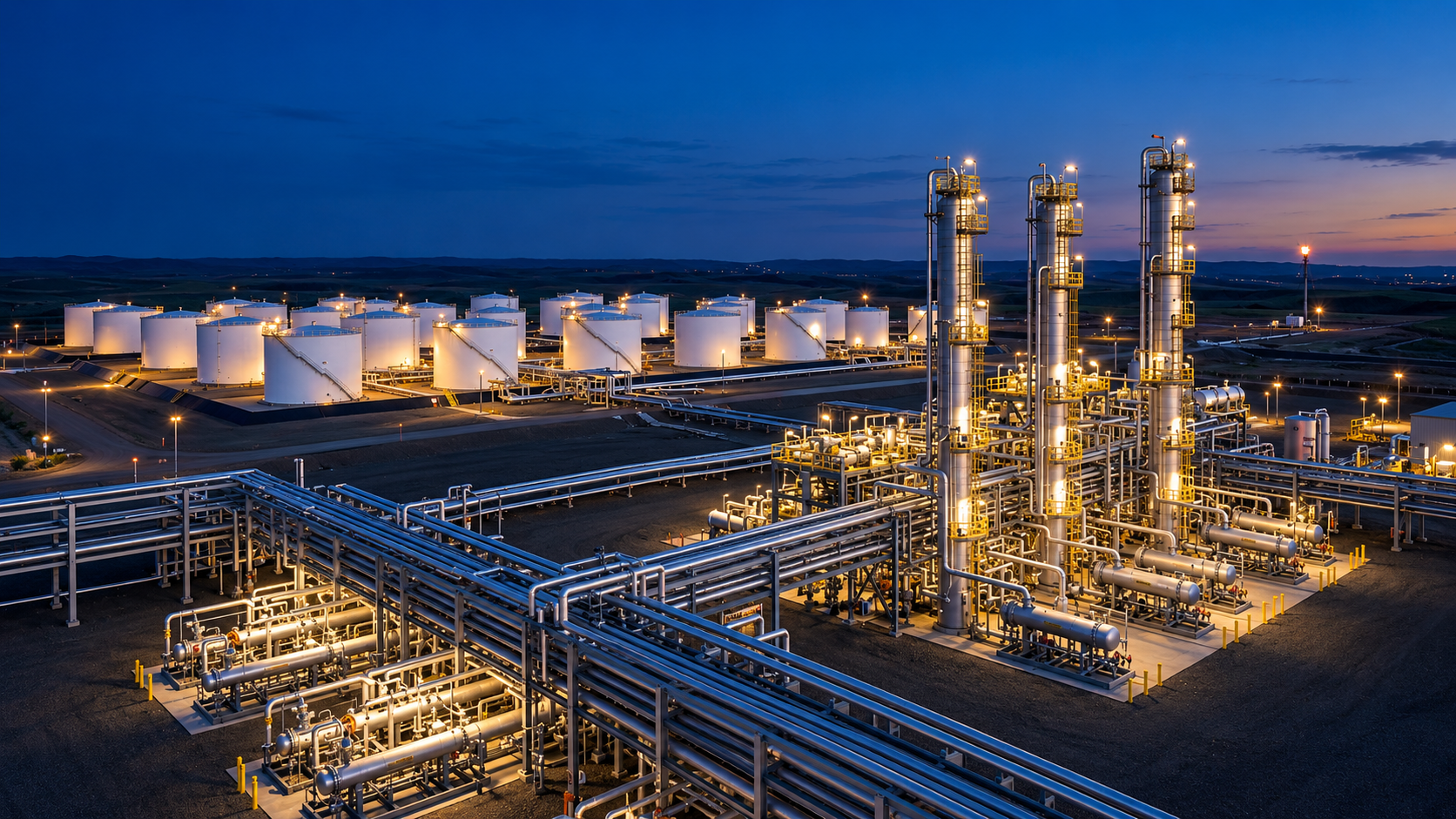
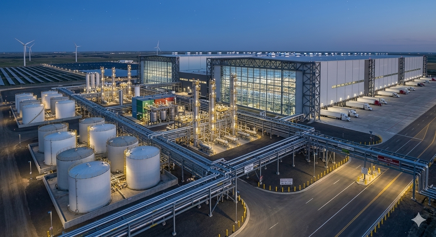
A terminal links storage, transfer, containment, corrosion control, inspection, instrumentation, maintenance, and people into one operating system. SOUBEL follows the interfaces where condition, evidence, ownership, and operating consequence meet.

THE TERMINAL SYSTEM

Integrity follows the product, the equipment, and the decision path.

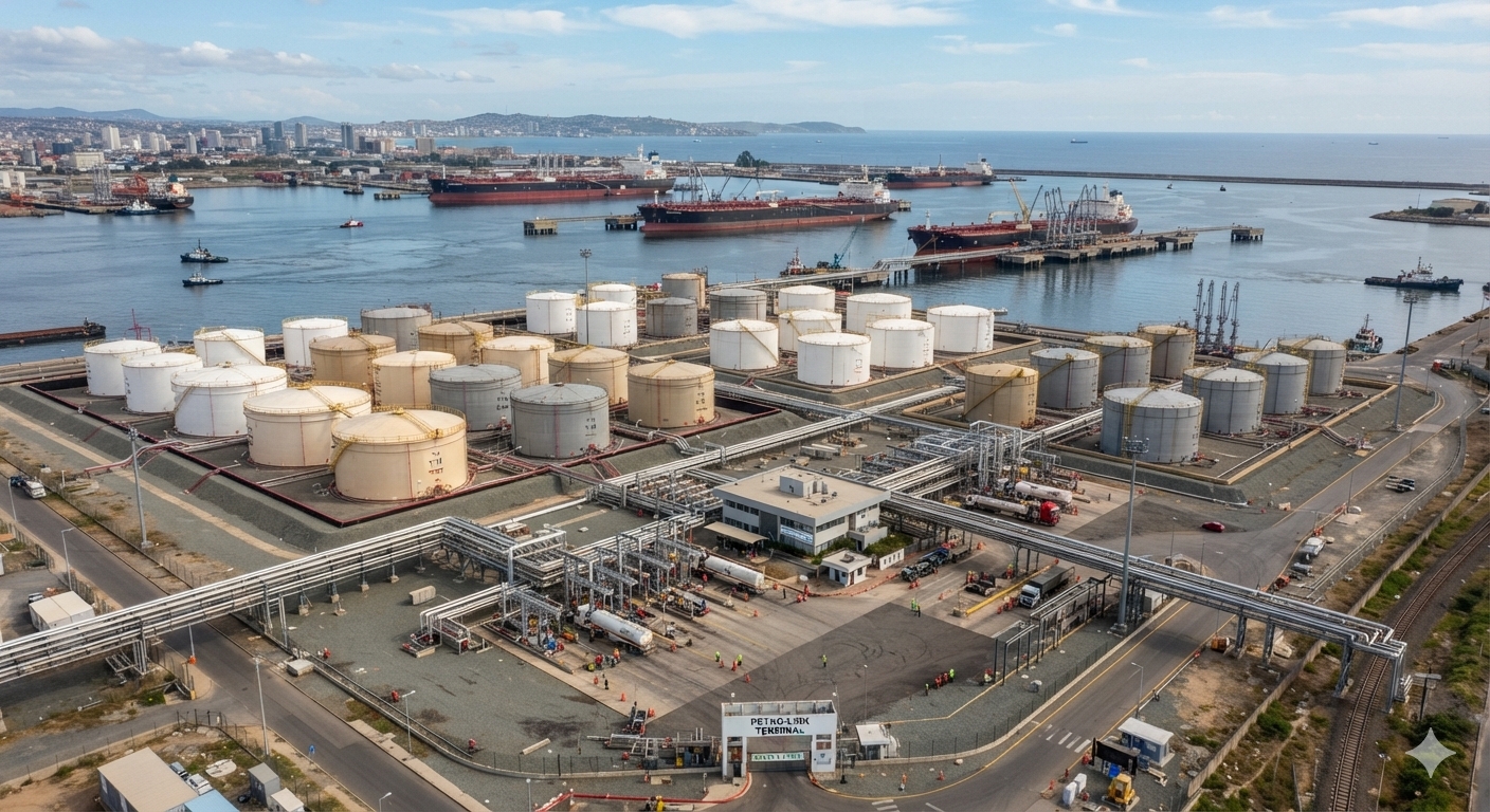
Receipt, storage, transfer, loading, containment, and response depend on assets that share operating conditions and consequences. A useful integrity view keeps those relationships visible as condition changes and work moves across disciplines.

ReceiptStorageTransferLoading / UnloadingContainment & Response
Storage interface

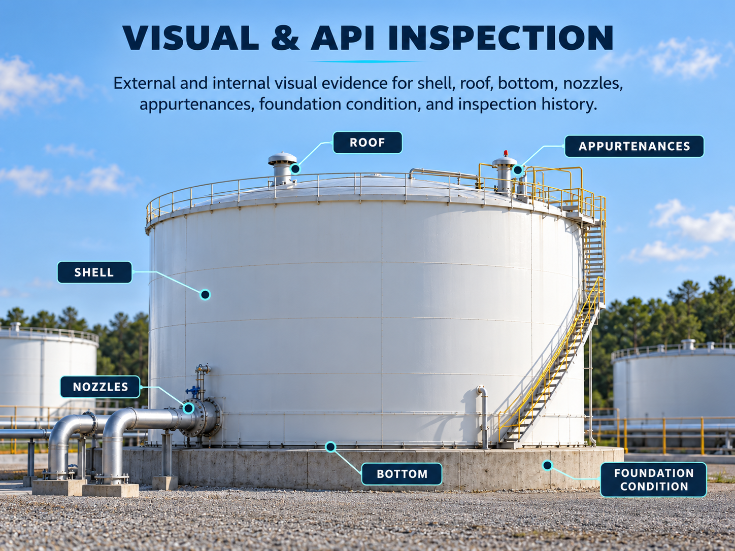
Tank bottom, shell, roof, foundation, product, water, coatings, corrosion control, nozzles, seals, and appurtenances.

Transfer interface

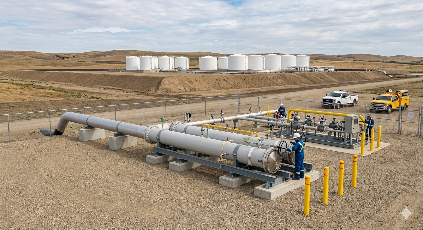
Piping, pumps, valves, manifolds, meters, loading systems, buried connections, supports, and mechanical equipment.

Control interface

Level measurement, alarms, overfill prevention, interlocks, shutdown functions, monitoring, and operating procedures.

Execution interface

Inspection, engineering, operations, maintenance, contractors, repair, verification, records, and return-to-service decisions.

STORAGE TANK INTEGRITY

A tank carries several integrity stories at once.

Tank integrity is shaped by geometry, materials, service, environment, inspection history, corrosion, settlement, repairs, operating changes, and the condition of connected systems. Each part of the tank contributes different evidence.

BOTTOM & FOUNDATION

Condition below the product line can control the decision.

Bottom-plate thickness, soil-side exposure, water and product-side corrosion, foundation condition, drainage, settlement, prior repairs, lining history, and cathodic-protection performance can all affect remaining integrity.

SHELL & ROOF

Geometry, corrosion, and service history matter together.

Shell thickness, welds, nozzles, roof condition, floating-roof systems, seals, drainage, atmospheric exposure, coating condition, distortion, and operating history contribute to the condition picture.

APPURTENANCES & CONNECTIONS

The tank boundary includes the places where systems connect.

Nozzles, piping interfaces, mixers, gauges, vents, ladders, platforms, roof penetrations, grounding, instrumentation, and other attachments create their own inspection and maintenance questions.

CORROSION ACROSS THE FACILITY

Corrosion changes as the exposure changes.

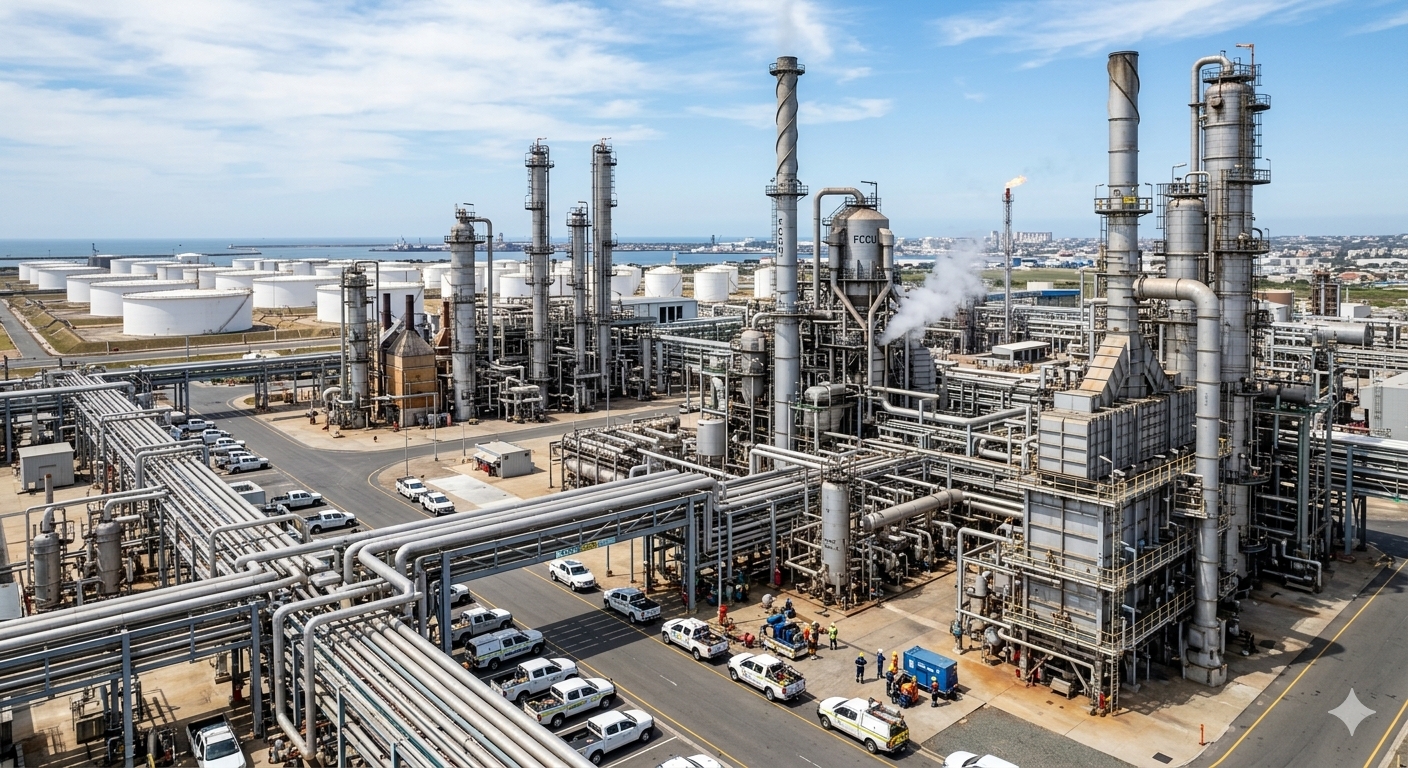
A terminal can place steel against soil, atmosphere, product, water, coatings, linings, insulation, concrete, and electrical systems within the same operating facility. Corrosion management depends on recognizing the environment and mechanism behind the evidence before selecting the response.

TANK BOTTOM & FOUNDATION

Soil-side and internal exposure can tell different stories.

Foundation moisture, soil chemistry, drainage, bottom configuration, coatings, cathodic protection, internal water accumulation, product chemistry, lining condition, and prior thickness history can shape bottom-corrosion risk.

SHELL, ROOF & ATMOSPHERE

External environment and coating condition remain visible.

Atmospheric exposure, water traps, roof drainage, seals, coastal or industrial environments, coating breakdown, crevices, and local geometry can create different corrosion patterns across the same tank.

TRANSFER PIPING

Buried and aboveground sections face different environments.

Internal service, dead legs, low points, external coatings, cathodic protection where applicable, atmospheric exposure, insulation, supports, drainage, and changing operating service all influence the evidence.

PROTECTION & VERIFICATION

Protection systems need evidence that they are performing as intended.

Coatings, linings, cathodic protection, monitoring, inspection, thickness history, field measurements, and repair verification become more useful when the operating and environmental context remains attached.

EnvironmentMechanismProtectionEvidenceDecision

INSPECTION & CONDITION EVIDENCE

The method should answer the integrity question.

Visual inspection, thickness measurement, floor scanning, weld and leak testing, dimensional surveys, settlement evaluation, remote inspection, and engineering assessment each contribute different evidence. The decision depends on capability, coverage, limitations, uncertainty, and how the result compares with operating and historical context.

VISUAL & THICKNESS EVIDENCE

Establish what can be observed and measured.

Visual condition, UT thickness, corrosion patterns, coating or lining condition, appurtenances, leaks, deformation, and service history help establish where additional evaluation may be needed.

BOTTOM ASSESSMENT

Floor condition requires appropriate coverage and interpretation.

MFL and other bottom-inspection techniques can support broad floor screening and characterization when capability, calibration, accessibility, confirmation methods, and limitations remain understood.

GEOMETRY & SETTLEMENT

Shape and support conditions can change the integrity question.

Settlement surveys, verticality, roundness, dimensional measurement, laser scanning, foundation observations, and historical comparison can help identify movement or distortion that warrants evaluation.

ENGINEERING ASSESSMENT

Inspection becomes decision support through qualified interpretation.

Fitness-for-service, remaining-life assessment, risk-based inspection, repair planning, and return-to-service decisions combine condition evidence with materials, loads, service, consequence, uncertainty, and governing criteria.

TRANSFER SYSTEMS

Integrity continues beyond the tank nozzle.

Terminal piping and transfer equipment carry product between storage and receipt or delivery points. Their condition affects containment, throughput, environmental exposure, maintenance planning, and the ability to safely isolate or respond when conditions change.

PIPING & MANIFOLDS

Configuration and service history shape the threat picture.

Aboveground and buried piping, dead legs, low points, supports, flanges, drains, vents, manifolds, previous modifications, and service changes all contribute to inspection and corrosion decisions.

PUMPS, VALVES & METERS

Mechanical condition affects both integrity and operability.

Leakage, vibration, sealing, isolation capability, pressure and flow behavior, maintenance history, materials, and connected instrumentation influence reliability and response.

LOADING & UNLOADING

Transfer interfaces bring equipment, controls, and people together.

Loading racks, arms, hoses, couplings, valves, grounding or bonding, metering, containment, alarms, procedures, and operator actions form a connected transfer boundary.

OVERFILL, CONTAINMENT & RELEASE PREVENTION

Prevention depends on equipment, controls, response time, and ownership working together.

Level information, alarms, independent protection layers, transfer procedures, containment, inspections, and emergency response each address a different part of release prevention. Their effectiveness depends on clear operating limits and a response path that survives the handoff.

OVERFILL PREVENTION

Reliable level information has to lead to prepared action.

Tank capacity, operating limits, level measurement, alarms, shutdown actions, transfer rates, response time, testing, maintenance, and accountability form the overfill-prevention system.

SECONDARY CONTAINMENT

Containment condition is part of facility integrity.

Dikes, berms, walls, floors, drainage controls, penetrations, valves, accumulated water, inspection findings, and maintenance affect how a facility limits the consequence of a release.

RELEASE RESPONSE

The response begins before the event.

Isolation capability, emergency shutdown, procedures, access, communications, spill planning, maintenance condition, and field readiness determine how quickly a facility can control and learn from a release.

LIFECYCLE & DIGITAL CONTINUITY

A terminal should remember what changed.

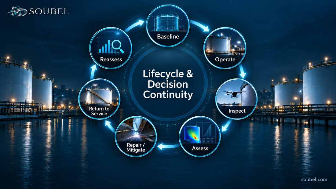
Design basis, construction and repair records, inspection history, tank geometry, corrosion rates, CP and coating history, operating service, alarms, modifications, transfer-system changes, field findings, and verification become more valuable when the facility can connect them over time.

BaselineOperateInspectAssessRepair / MitigateReturn to ServiceReassess

Integrity platforms, inspection databases, connected asset records, 3D models, monitoring systems, analytics, and digital twins can support continuity when source, asset identity, context, assumptions, and verification remain traceable.

AUTHORITATIVE CONTEXT

Different parts of the system are governed by different technical and regulatory sources.

SOUBEL provides orientation and connects the decision context. Current standards, regulations, company procedures, qualified technical authority, and asset-specific engineering govern requirements, calculations, acceptance criteria, inspection intervals, repair decisions, and compliance.

Regulatory applicability and standard requirements depend on facility, service, jurisdiction, asset configuration, and other conditions. Current primary sources should be verified for each specific decision.

THE TERMINAL INTEGRITY TEST

Can the organization trace condition and decision basis across the tank, transfer system, controls, containment, and the work that follows?

Operational Trust grows when evidence remains connected across the interfaces where terminal integrity is actually managed.